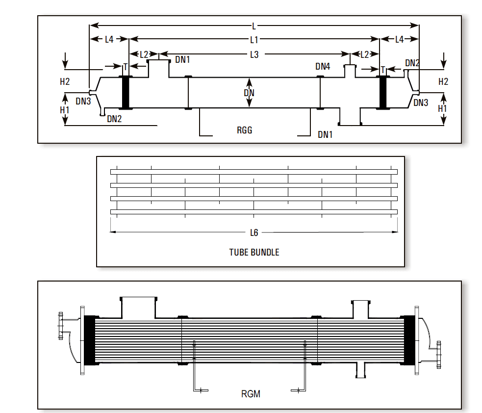
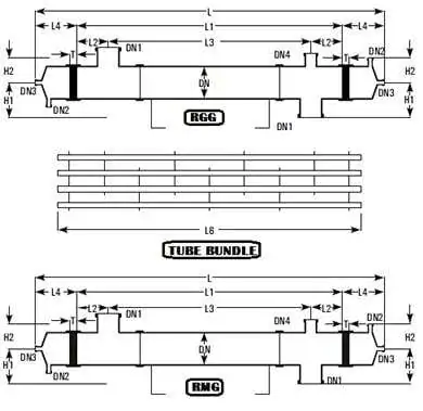
Dimensional Specifications of Shell and Tube Heat Exchanger :
Permissible temperature range for both shell & tube sides – 40° C to 150° C.
Maximum permissible temperature difference between shell & tube sides 120° C.
All sizes & models are suitable for full vacuum on both side. Maximum limiting pressures are tabulated here below :
| Maximum Permissible Pressure Range, Kg/cm2(g) | ||||
| Model | Side | 150DN | 225DN | 300DN |
| RGG | Shell Tube |
2.0 2.0 |
1.0 1.0 |
1.0 1.0 |
| RGM | Shell Tube |
2.0 3.5 |
1.0 3.5 |
1.0 3.5 |
| RMG | Shell Tube |
3.5 2.0 |
3.5 1.0 |
3.5 1.0 |
The above ranges of applications are admissible limiting values. For each specific case we recommends the admissible operating data based on the relations between pressure and temperature, size and model.
Shell and Tube Heat Exchanger Performance & Design Data :
The particular advantage of shell & tube heat exchanger is high heat transfer performance. The relation between heat transfer and velocity of flow can be easily seen in the diagram.
On receipt of the operating data from client the most favourable shell and tube heat exchanger is selected. This accurate design combined with most reliable quality assurance ensures economy and operational reliability for the user.
For approximate sizing some typical heat transfer coefficients are given here below :
| U-Values | |||
| Media | Use | kcal/m2hrk | W/m2k300 |
| DN | |||
| Steam water | condensation | 350-550 | 410-640 |
| Water – water | cooling | 250-350 | 290-410 |
| Water – air | cooling | 30-60 | 35-70 |